Hard shadows
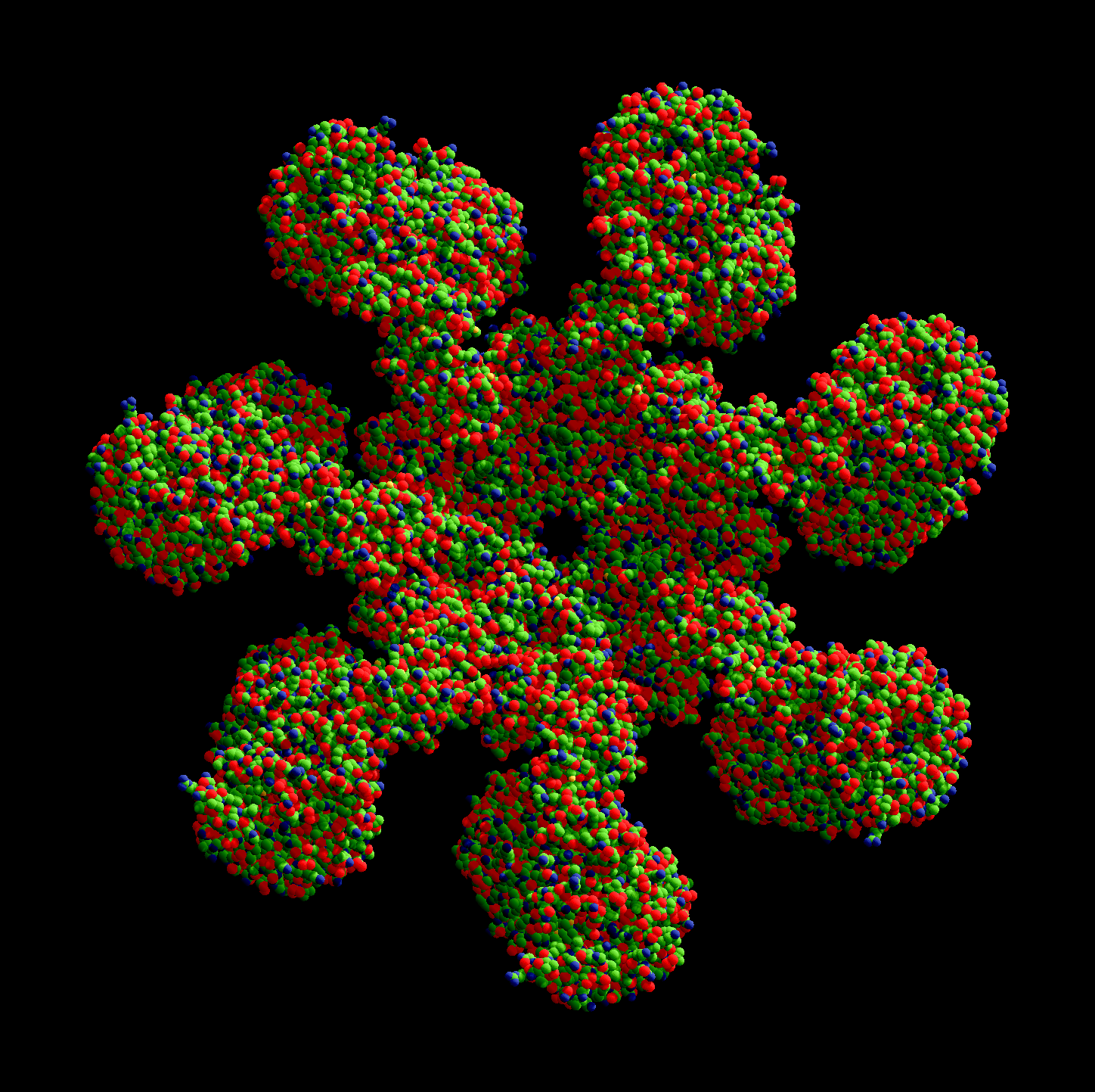
On a protein structure visualization tool, shadows are specially useful to convey the shape of the structure in a way our brain can interpret. This is readily apparent in the figures presented in Marco Tarini, Paolo Cignoni, and Claudio Montani, Ambient Occlusion and Edge Cueing to Enhance Real Time Molecular Visualization, the paper that inspired this project’s shadow implementation (which actually implements ambient occlusion, not dynamic shadows, that’s why I said ‘inspired’).
How it’s done
Step 1
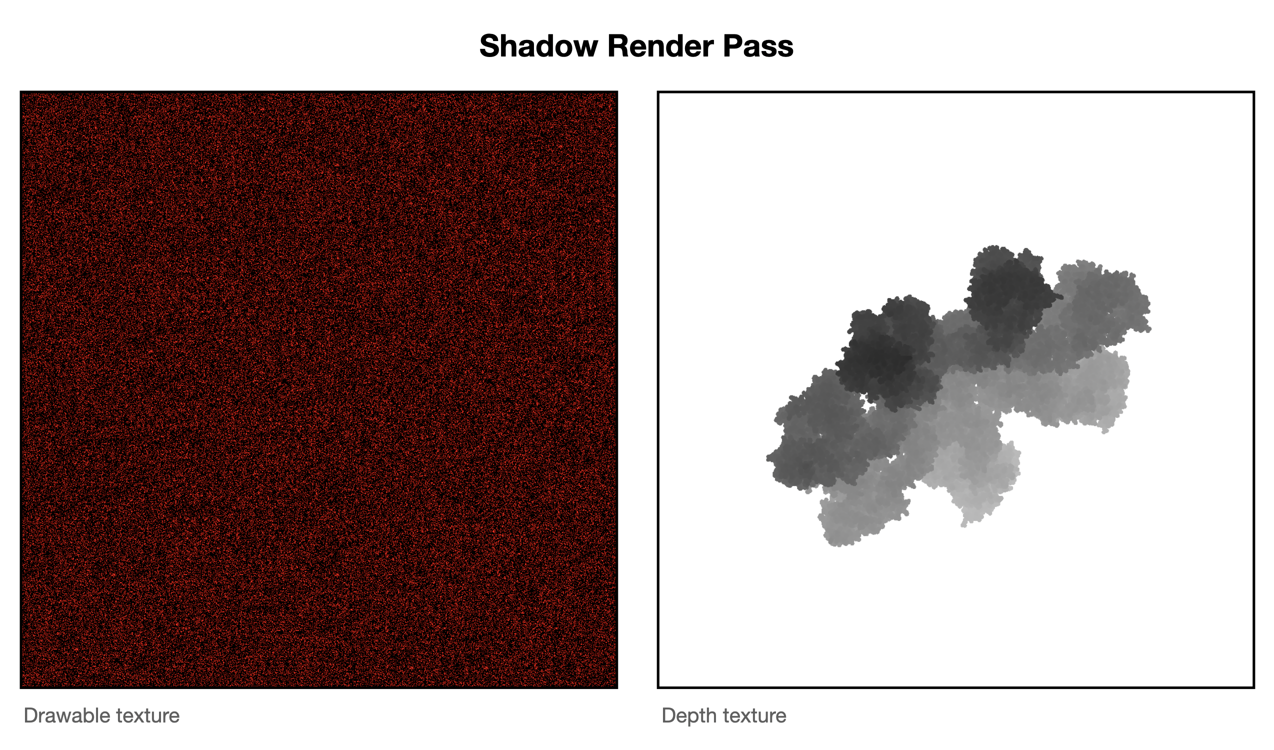 The first step is to create a texture with the depth information of the structure as seen from the sun’s frame of reference. This uses an orthographic projection, since we approximate the sun as being infinitely far away an thus their rays being perfectly parallel (hence, an orthographic projection). This projection must fit the structure as tightly as possible, but avoiding leaving any part of it oustide the frame. Parts of the structure not seen on the main camera can still cast shadows seen on that camera.
The orthographic’s projection near and far planes must be as tight as possible too. While we could generate a texture using near and far planes much further appart than required, the depth values would be compressed in a much smaller range (for example, ranging between 0.45 to 0.55 instead of the ideal 0.0 to 1.0). This causes a loss of precision that can cause shadow acne later on.
Since we are using impostor geometries to render the scene, we have to invoke the fragment shader to create the depth texture. To do that, we create a temporary texture, the equivalent of the final drawable texture on the normal render pass, so the fragment kernel gets called for each pixel of the image. Since we don’t need this texture data (just the corresponding depth map), we can make this texture loadAction = .dontCare and storeAction = .dontCare. Also, on TBDR GPUs we can mark this texture storageMode = .memoryless too.
Step 2
 After the render pass in Step 1 renders the depth texture, we enqueue the render pass that draws the impostor geometries (the spheres). During the fragment function, we convert the coordinates of the sphere from camera space to the sun’s frame of reference, in the same way we did in Step 1.
simd_float4x4 camera_to_shadow_projection_matrix = frameData.camera_to_shadow_projection_matrix;
float3 sphereShadowClipPosition = (camera_to_shadow_projection_matrix * float4(spherePosition.x,
                                                                               spherePosition.y,
                                                                               spherePosition.z,
                                                                               1.0)).xyz;
To be able to sample the sun’s frame depth texture we need to convert the coordinates from Metal’s Normalized Device Coordinates (NDC) to Metal’s texture coordinates. To do that, we use:
sphereShadowClipPosition.y *= -1;
sphereShadowClipPosition.xy += 1.0;
sphereShadowClipPosition.xy /= 2;
Then, we make a depth comparison using sample_compare. The shadow depth texture on the sun’s frame of reference contains the depth of the closest occluder for a given x and y on that frame of reference. If the point seen in the camera render pass has a depth value greater than the one saved in the texture for the x and y values of that point in the sun’s frame of reference, it means that it’s occluded.
float shadow_sample = shadowMap.sample_compare(shadowSampler,
                                               sphereShadowClipPosition.xy,
                                               sphereShadowClipPosition.z);

bool is_sunlit = false;
if (shadow_sample > 0) {
    is_sunlit = true;
}
If it’s occluded, we substract some light from the final color of that pixel, creating the shadows.
shadedColor.rgb -= frameData.shadow_strength * (1 - is_sunlit);
Step 3 (Optional) - Soften shadows
 Directional shadows are hard. Since the resolution of the texture we use for the depth texture on the sun’s frame of reference is limited, what we use to cast the shadows is not a perfect circle/sphere, but a ‘pixelated’ version of it. Think of when you create a circle in Minecraft using just a few blocks.
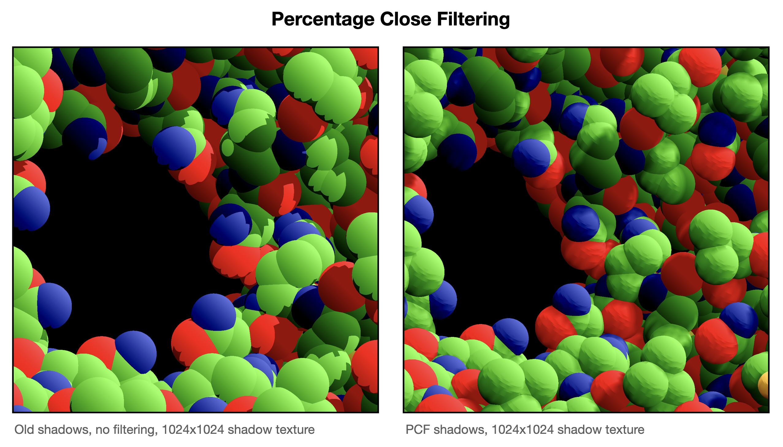
When the shadows are cast from that pixels, aliasing problems appear. Specially if you cast them onto surfaces that are almost tangential to that direction (the sphere’s sides, in out case). There are some cool algorithms to fix this problem, the coolest of them probably being Variance Shadow Maps (VSMs), which models each pixel as a distribution (of depth values) and uses the variance (the squared depth) to estimate the bounds of the distribution by recovering the moments of the distribution. But I digress. This cool method causes unwanted light leaks when there are too many occluders for a single x and y region (depth complexity). Since the pathological case for this algorithm is the expected case for our application, we have to discard this approach. Instead, we use what’s called Percentage Close Filtering. Essentially, when sampling the sun’s depth texture in Step 2, we sample neighbouring texture pixels and make an average, thus creating a soft shadow terminator.
As seen on the image, there are still some problems with the shadows that are not solved with PCF, but it’s definitely a huge improvement. This is the code used to sample the texture using PCF (we call this instead of the previous code snippet containing sample_compare in Step 2):
float sunlit_fraction = 0;
constexpr int sample_count = 2;
for (int sample_index = 0; sample_index < sample_count; sample_index++) {
    // VogelDiskSample may be called with a random number instead of 0 for the rotation
    half2 sample_offset = VogelDiskSample(0.001, sample_index, sample_count, 0);
    sunlit_fraction += shadowMap.sample_compare(shadowSampler,
                                                sphereShadowClipPosition.xy + float2(sample_offset),
                                                sphereShadowClipPosition.z);
}
And then we subtract the color like this:
shadedColor.rgb -= frameData.shadow_strength * (1 - sunlit_fraction / sample_count);
You may be wondering wtf is a Vogel Disk and why we call it to compute the offset. This is the Vogel Disk function:
half2 VogelDiskSample(half radius_scale, int sampleIndex, int samplesCount, float phi) {
    half GoldenAngle = 2.4f;

    half r = radius_scale * sqrt(sampleIndex + 0.5f) / sqrt(half(samplesCount));
    half theta = sampleIndex * GoldenAngle + phi;

    half2 sine_cosine;
    sincos(theta, sine_cosine);

    return half2(r * sine_cosine.y, r * sine_cosine.x);
}
But why are we calling such an expensive function instead of making the offset be, for example, along the x and ycoordinates? There’s a sqrt and a sincos function in there, it’s almost as ALU intensive as the rest of the fragment funcion. Or is it?
Truth is, making the offset along the x and y directions didn’t look good in practice. It’s aligned with the pixels in the sun’s depth texture, so it probably caused another kind of aliasing problem where the samples had an unfair probability of sampling the same pixel on the texture. The Vogel Disk looks much better in practice. A Vogel Disk sample is typically called using a random number for phi, to completely vanish any probability of aliasing problems when sampling the sun’s depth texture. That’s because Vogel Disk’s have a nice property: if you create a Vogel Disk with N samples and φ rotation, and another Vogel Disk (of the same number of samples and radius, and the same center), but with φ + δφ rotation, with δφ being any angle other than 2π (or a multiple of it), none of the samples of the second disk overlap any of the samples of the first disk.
Anyway, it looks like calling it with a random angle made little difference in practice, and calling it with phi = 0 didn’t tank performance. Why? Well, the loop is likely to be unrolled by the compiler for any reasonable number of samples. When the loop is unrolled, all the arguments of the function VogelDiskSample are known at compile time, so the calls to the function can be computed at compile time and replaced with constant values. No need to compute the expensive sqrt and sincos functions at runtime!
So essentially we’re just using the Vogel Disk to take two samples at an angle that doesn’t cause aliasing problems with the sun’s depth texture. We can just hardcode the angles, but leaving it like this opens the door to calling it with a random phi value in the future (maybe in a non-realtime high-quality render like a ‘photo mode’).
Gotchas
Shadow acne
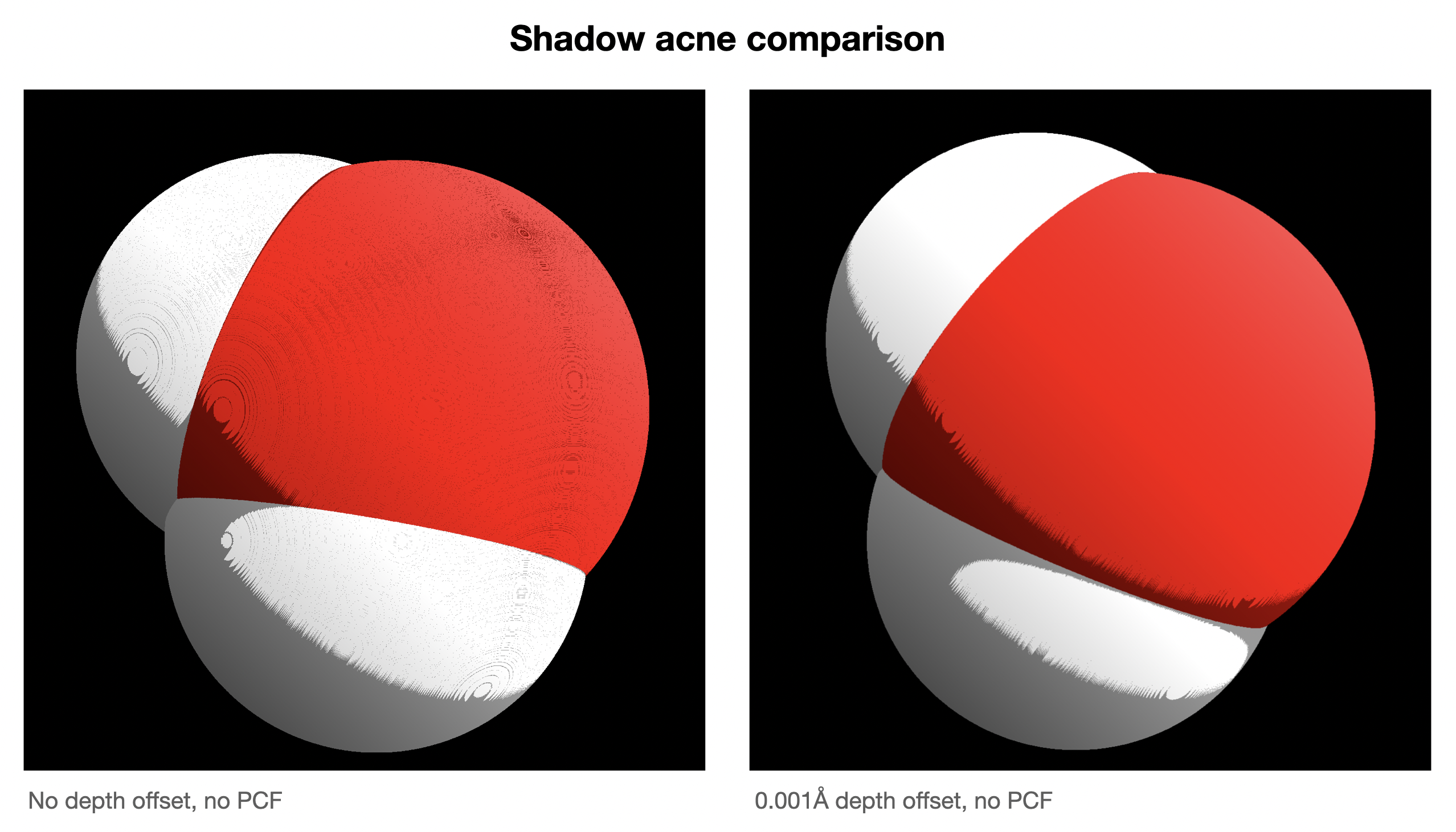 This is solved applying a small offset when computing the depth from the sun’s frame of reference (Step 1). It’s caused by the sampler in Step 2 returning a depth value just below the one stored in the texture created in Step 1 due to floating point precision issues.
We basically tell the shader in Step 1 to ‘lie’ and say that everything is a tiny amount (in out case, 0.001Å) further than it really is, so the sample_compare doesn’t fail due to comparing two extremely similar values and not having enough floating point precision.
If you look at the comparison image, the upper right part of the oxygen (red) atom should be completely lit, but if we apply no offset (left image), a weird shadow pattern emerges due to accidental self-shadowing because of the floating point precision issues. The depth offset fixes it (right image). The shadow terminators in both images look weird too, but that’s due to the aliasing issue mitigated in Step 3 with PCF (which this images don’t have).
Adding PCF back in causes some self-shadowing to reappear for the usual 1024x1024 shadow texture resolution. However, this is not an issue for the normal viewing experience, and we can increase the texture resolution and sample_count used for PCF, and get this smooth-as-f*ck image (expensive to render, non-realtime for large proteins but suitable for a near-realtime ‘photo mode’):
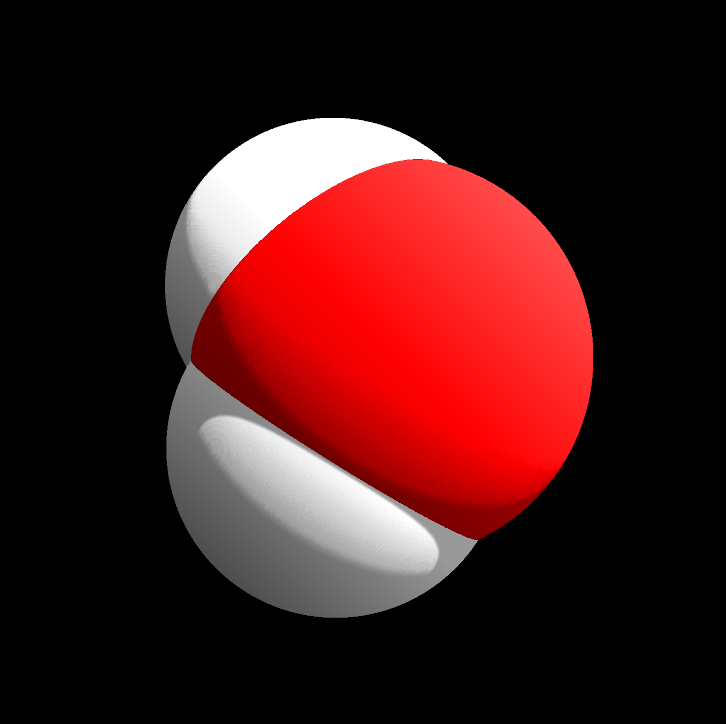
Simply using a high resolution shadow texture and a high sample_count alone without the depth offset didn’t quite get the image to look as smooth due to the self-shadowing artifact.